Project types
Following project types can be created and processed:
Projects can be converted to different type too (e.g. using a 2D model as a template for more sophisticated 3D modelling).
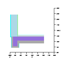
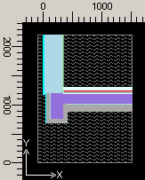
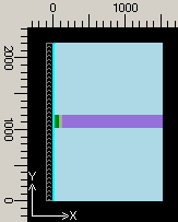
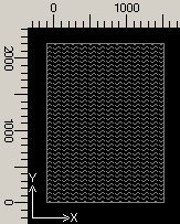
2D project
Primary property of a 2D project is given by geometric modelling done in two dimensions only. Only one planar slice is entered and the resulting two dimensional construction calculated. There is no input regarding the third dimension - i.e. coordinates of the axis perpendicular to project plane.
This project type is typically used to model a linear thermal heat bridge.
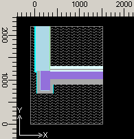
Final 2D Projekt contains ordered sequence of elements. The order of elements is relevant, because later entered elements will partly or fully overlap elements earlier in the order if covering common plane area.
Note: Internally AnTherm represents the 2D model as a single layered 3D project with the thickness of exactly 1000 mm - i.e. 1,0 m - in Z direction.
This dependency shall be considered if, e.g. for some result display, two dimensional contractions are modelled in three dimensions.
Remark: To support graphical entry the underlay can be registered and shown within the plane of Elements2D window.
Remark: The 2D Project Type will be often uses as a starting point for creating 3D models by various conversion capabilities (see below) .
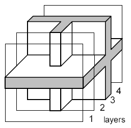
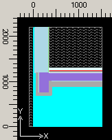
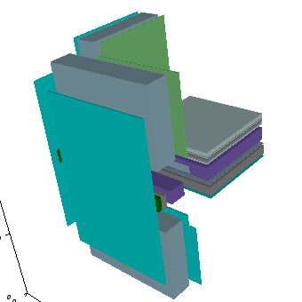
Layered 3D project
Primary property of a layered 3D project is given by its geometric modelling of planar slices consecutive to each other (slices itself are identical to a 2D project type).
This project type is typically used to model a point thermal heat bridge.
Three dimensional model is given by assigning a thickness to each
such planar slice.
In Antherm each such slice with assigned thickness is called leyer.
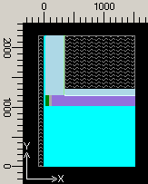
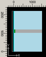
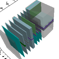
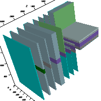
Final "layered 3D project" contains ordered series of layers. The sequence can be controlled by the layers list.
Note: A three dimensional model will result in exactly same results as its two dimensional counterpart only, and only if, the geometry and conductivities do not change along one dimension and the extent in this direction is exactly 1000 mm - i.e. 1,0 m.
Remark: To support graphical entry the underlay can be registered and shown within the plane of Elements2D window.
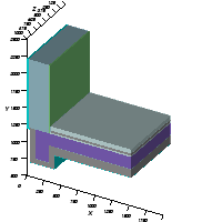
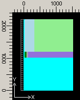
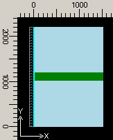
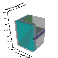
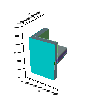
3D project
Primary property of a 3D project is given by entering all three coordinates in three dimensions directly. The resulting geometry of building construction is described by series of cubes.
This project type is typically used to model a complex point thermal bridge.
Note: A three dimensional model will result in exactly same results as its two dimensional counterpart only, and only if, the geometry and conductivities do not change along one dimension and the extent in this direction is exactly 1000 mm - i.e. 1,0 m.
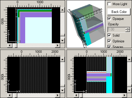
Remark: To support graphical entry three underlays can be registered and shown within respective planes of Elements23 window quadrants.
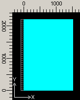
Converting between project types
- A 2D project can be transformed (converted) to a layered 3D project.
-
A 2D project can be revolved (rotated) to produce 3D project based on a 2D template.
Warning: Revolution to a 3D project is irreversible. - A layered 3D project can be converted to a 2D project only if it contains only one layer.
-
A layered 3D project (and a
2D project too) can be converted to a
3D
project
.
During the conversion AnTherm will assign each element to a additional group named „Layer#:LayerName/Thicknessmm“. This allows element selection by its original (prior to conversion) layer structure ( context menu of element processing->Select->By Group ).
Warning: Converting to a 3D project is irreversible. - A 3D project can be converted to a 2D project only if thicknesses (e.g. Z coordinates) of all elements are equal. The resulting project will receive thickness of 1000mm (Z1=0, Z2=1000).
-
A
3D
project
can be converted to a
layered 3D project. The conversion will
create 3D Layers in the Z-directions for all Z-coordinates existent in the
project. Layer names will be derived from that Z-coordinate values. All
elements are then added accordingly to respective layers.
Warning: This conversion need not be reversible.
Important: Element of Z-thickness equal 0mm will not be included in the conversion and ignored.
See also: Create new project, Converting a project, Working with files, 3D-Layered model