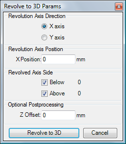
Revolve to 3D Params - dialog
 The conversion by revolution of a
2D project to
3D model is defined by the parameters provided in this dialogue window.
The conversion by revolution of a
2D project to
3D model is defined by the parameters provided in this dialogue window.
A 3D model is constructed by revolving the 2D object by 90° around vertical or horizontal rotation axis placed in the plane of the 2D model. The position of the axis relative to the 2D model defines the resulting 3D constructions. The option of clipping the 2D model to one side of the axis is also provided.
Important: Remember to save the originating 2D model prior to executing the revolution. The operation is not reversible and cannot be undone.
| Revolution Axis Direction | Defines the orientation of the rotation axis the revolution shall be performed around. Choose either X (horizontal) or Y (vertical) axis direction. |
| Revolution Axis Position | Sets the position of the axis in absolute coordinates. Typically it will be some adiabatic boundary at some model extent or any arbitrary position for specialized purposes. |
| Revolved Axis Side | Elements of the 2D model revolved are clipped to either side of the axis. If only one side is chosen for revolution elements clipped for the other side are not revolved. |
| Z Offset | The resulting 3D model is constructed in such a way, that the Z position of the revolution axis will be kept equal with the axis position specified at first. Z Offset adds a post processing option to shift all resulting Z coordinates in the 3D model by the offset specified. |
| Revolve to 3D | Executes the revolution using the current set of parameters |
| Cancel | Aborts the operation |
Examples
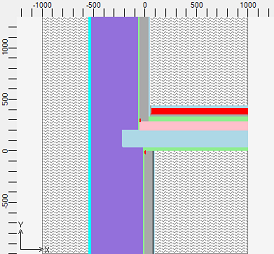
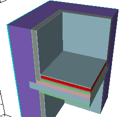
Example 1: Following 2D model is once converted by revolution around the X axis at Y=2000mm (which is coincident with the adiabatic boundary at the top of the 2D model)
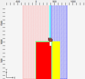
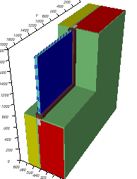
The model below results from the same 2D model revolved around the Y axis at X=-1000 mm.
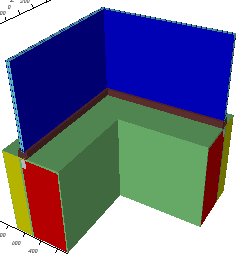
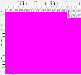
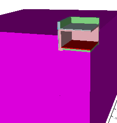
Example 2: The 2D model of a wall & floor junction (shown below) is revolved around the Y axis at X=1000 mm producing a 3D corner component available for further detailed modelling and thermal assessment.
Example 3: Component in connection with ground was prepared in 2D at first and then revolved to 3D (rotated around Y axis at X=4475 mm).
See also: Convert projects, Project types