Elements 2D - window
 The
Elements 2D window, together with
element list and the
element editor provide the central front
end of the application used for data input of a modelled building construction
component. Pressing the right mouse button exposes the context menu
offering all
element editing
functions
.
The
Elements 2D window, together with
element list and the
element editor provide the central front
end of the application used for data input of a modelled building construction
component. Pressing the right mouse button exposes the context menu
offering all
element editing
functions
.
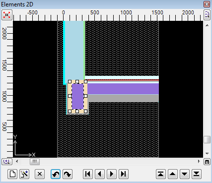
The Element 2D window shows graphically the list of all input elements (or elements of the active 3D-layer ) in the specific order of overlapping.
Remark: This window has its primary use for 2D- and 3D-layered models only. For pure 3D models it will only show the Z-view onto the model - thus it is advised to use the Elements 23 window to process pure 3D models.
On one hand the window provides an instant graphical view onto the component
under construction. On the other it is used as an interactive input device
together with the mouse as a tool to edit current construction. Graphical sizing
of elements is supported with the snapping grid. From this window
one can select elements for processing, add new elements, change the overlapping
order (promote or relegate) of elements or delete them.
The
2D view can be copied onto
the clipboard
to be pasted later
into another application (e.g. Word) from the clipboard - for example for
the purpose of integrating this view into some user's report. The image can be
saved to a picture file
also.
Remark: Functions offered in this window are by far comparable to those offered by Element selection (browser) window , because both windows show the same list of elements , but in two different representations - graphical and textual.
| Element graph | Graphical representation of all elements input (or elements of the active layer ) in the specific order of overlapping. |
| Inserts a new element (of type "Empty") to the end of the element list . | |
|
Inserts a copy of currently selected element(s) into the
element list
. Further details on duplicate function are provided in the description of the context menu of element editing functions . |
|
|
Deletes selected element(s) from the list. After deleting one selected element the selection move to the one before the deleted. When first element has been deleted the one becoming first after deletion is selected. If more then one element are selected actual deletion is executed if additionally confirmed by the user. See also: Cut elements to clipboard |
|
 Undo Undo(Ctrl-Z) |
Undoes (reverts) the latest action(s) in the given
editing context
. |
 Redo Redo(Ctrl-Y) |
Redoes (reapplies) the action lately undone in the given editing context. |
|
|
Selects an element which is first, previous to the currently selected, next to it or last in the element list. |
|
|
Reorders selected element(s) in the
element list
to the "backmost" position. The element is then located
at the beginning of the list thus now being
potentially overlapped by
all other elements. If more elements are selected then each one is relegated by the same distance as the backmost selected one. This action is inhibited if the chosen element does already occupy the first (backmost) location in the list. |
|
|
Reorders selected element(s) in the
element list
one position
"backwards". The element is then located earlier in the list thus now being
potentially overlapped by
another element which have thus been promoted to the location of the element
relegated. If more elements are selected then each one is relegated by one position in the list order. This action is inhibited if the chosen element does already occupy the first (backmost) location in the list. |
|
|
Reorders selected element(s) in the
element list
one position
"towards front". The element is then located later in the list thus now
potentially overlapping
another element which have thus been relegated to the location of the
element promoted. If more elements are selected then each one is promoted by one position in the list order. This action is inhibited if the chosen element does already occupy the last (front most) location in the list. |
|
|
Reorders selected element(s) in the
element list
to the "frontmost" position. The element is then located
at the end of the list thus now
potentially overlapping all other elements. If more elements are selected then each one is promoted by the same distance as the frontmost selected one. This action is inhibited if the chosen element does already occupy the last (front most) location in the list. |
| Click right mouse button | Exposes the context menu of element editing functions |
| Click left mouse button | Selection of an element in the element list for further processing. |
Turning the mouse wheel
|
The view will be "scaled" - displayed area will be zoomed. Remark: The scaling operation focuses around the mouse pointer. This allows zooming of the area of interest directly followed by ability to pan the view with the mouse. Remark: If one of the scrollbars has focus, then turning the mouse wheel will result in scrolling (instead of zoom). Remark: During drag operations of the editing mark the function of scaling by the wheel mouse turns is suspended |
 Fit Fit |
The position (scroll) and scaling (zoom) of the view will
be adjusted to display the whole component in the window. Remark: If there is an underlay registered and visible its bound will be taken into account also. |
| Drag with left mouse button depressed (not on the edit marker) |
The view will be „scrolled“ - displayed area is panned
following the mouse. Remark: You can use scroll bars to pan the view also. |
| Drag with left mouse button depressed (on the edit marker) |
Translates the element or changes the position of element's
side or its corner. Remark: If snapping grid is active, translations are adjusted to valid snapping grid line positions also. |
| Double-click left mouse button | Selection of an element in the element list and exposing the Element editor window for that selected element. |
| Click CTRL+left mouse button | Extend the selection with the one element clicked or removes the element clicked from the current selection |
| Drag SHIFT+left mouse button | Selection of element(s) with a lasso |
| Drag SHIFT+CTRL+left mouse button | Extending the selection of element(s) with a lasso |
| CTRL+C, CTRL+X, CTRL+V | Copy or Cut selected elements to the clipboard or Paste elements from the clipboard. |
 Copy
Image Copy
Image
|
Allows
saving
of the image to a picture file
(PNG,
TIF, JPG, BMP, GIF) and places the image onto the clipboard. See also: application setting "clipboard image Save-To-File option" |
The graphical display
The window displays a 2-dimensional slice through the building component. Elements are drawn in the order of their appearance in the element list . This results possibly (and as desired) in the effect of overlapping of elements being immediately visible on the screen.
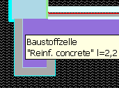 When
the mouse pointer hovers over one element the properties of the element under the
pointer are shown in a tooltip (small informational popup window). The
information shown applies to the visible (i.e. not overlapped) element. The tooltip text disappears after 5 seconds or on any mouse movement or click.
When
the mouse pointer hovers over one element the properties of the element under the
pointer are shown in a tooltip (small informational popup window). The
information shown applies to the visible (i.e. not overlapped) element. The tooltip text disappears after 5 seconds or on any mouse movement or click.
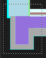
Each element is displayed differently depending on its element type and defined colouring:
- material elements are shown filled in their defined colour
- empty elements are shown as edge line surrounding the „empty area“ and with two diagonal lines
- space elements are filled with waved lines
- power source elements are filled with a fine net of lines and coloured in red
 Due
to the overlapping effect (which is also desired) one or more elements might be
fully obscured and thus not visible at all. Such (fully obscured) elements are
emphasized with a selection marker only if they are
selected in the element list.
Due
to the overlapping effect (which is also desired) one or more elements might be
fully obscured and thus not visible at all. Such (fully obscured) elements are
emphasized with a selection marker only if they are
selected in the element list.
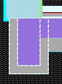
Selected elements are emphasized with selection markers. When only one element is selected a editing marker is shown instead and can be used to size or move that one element.
Remark: Line representation used to show elements with zero extent might be too thin at smaller view scaling and not visible. Such elements are visible only when selected.
The display can be adjusted according to users needs as required:
- Scrollbars allow panning of the view (which is also possibly by simply dragging the view with the mouse).
- Turning the mouse wheel will scale the view around the point below the mouse pointer (enlarged or shrunken).
- The fitting function adjusts the position and scaling in such way, that the whole construction is visible within the window.
- The colour of the background (which is by default set to black) can be changed within the application setting "Background 2D-colour" .
- A registered image can be displayed as an underlay or as partly transparent overlay for better orientation during creation of the model.
Element selection
One or more elements in the element list can be selected. Selection can also be performed within the graphic view in this window:
- by using the lasso function one can select many elements for further processing
-
a mouse click while the mouse pointer rests over one element will select
that element which then will be emphasized with an
editing marker
.
Remark: If there are more elements stacked below the mouse pointer, each next mouse click will select the one behind the one currently selected (i.e. in the opposite order to the overlapping sequence). - a mouse click while the control key (CTRL) is depressed will add the element below the mouse pointer to the list of selected elements.
-
by element selection buttons
 to select single elements from the
element list.
to select single elements from the
element list.
Lasso
 The
lasso provides the function for selecting elements
for further processing.
The
lasso provides the function for selecting elements
for further processing.
The lasso function will be activated when the shift-key (SHIFT) is held depressed together with left mouse button typically followed by dragging the mouse.
All elements fully inside of the lasso will be selected when the mouse button is returned to its resting position.
When the control key (CTRL) is also held depressed (SHIFT+CTRL+left mouse button) the selection will then be extended with elements matched with lasso.
To cancel the lasso selection process (i.e. to keep the last selection active) simply free the SHIFT key while the mouse button is still kept depressed.
Moving of multiple elements
Holding down the Ctrl key, the left mouse button and dragging the mouse triggers the movement of multiple elements.
Element processing
A double click with the mouse over an element will open the processing window designed for elements - the element editor.
When the right mouse button is depressed in the graphical window, the context menu of element processing is exposed offering extensive list of element processing functions for choice.
Elements can be selected with a single mouse click or with the lasso function .
If there is only one element selected its position can be changed by dragging the editing marker with the mouse.
 Functions
of the context menu
Functions
of the context menu
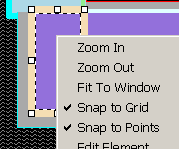
|
Zoom In Zoom Out |
The view can be „scaled“. This is an alternative to using the mouse wheel. |
| Fit to window | Adjust the position and scaling in such way, that the whole construction is visible within the window. |
| Snap to Grid |
The function of the snapping grid
will be turned on or off. The "check mark" shows the active setting of this function. See also: Snapping grind parameters |
| Snap to Points |
This is a snapping function,
which snaps to already existing coordinate points and can be turned on or
off here. The "check mark" shows the active setting of this function. See also: Snapping grid parameters |
| Snap-To-Grid params... | Shows the dialog used to adjust current snapping grid settings . |
| Underlay/Overlay→ |
Functions respective to underlay/overlay. Remark: The planar underlay is registered at the plane shown within the window. Within the context of Elements23 window (i.e. a 3D-Project) up to three underlays can be registered within respective quadrants. |
|
Underlay/Overlay→ Image Register |
Offers the dialog "Register Underlay Image" to import an image file . |
|
Underlay/Overlay→ Image Hide |
If there is an underlay image registered and shown it will be hidden. |
|
Underlay/Overlay→ Image Drop |
If there is an underlay image registered its registration data will removed from the current project. |
|
Underlay/Overlay→ Image Underlay |
If there is an underlay image registered it will be shown as underlay (being occluded by elements entered). |
|
Underlay/Overlay→ Image Overlay 100% Image Overlay 50% Image Overlay 20% |
If there is an
underlay image
registered
it will be shown as overlay (occluding elements entered)
either opaque (100%) or with 50% or 20% of transparency value. The currently selected transparency value is marked with a checkmark left to the menu item. See also: Dialog "Register Underlay Image" to import an image file |
Many further functions of this context menu are common to all element processing windows and are described separately .
Editing marker
![]() The editing marker is used for adjusting the position of one element. It is
displayed as rectangle emphasized with a thick coloured edges.
The editing marker is used for adjusting the position of one element. It is
displayed as rectangle emphasized with a thick coloured edges.
Dragging an edge with the mouse will translate (move) the complete edit marker
(and thus the element will also move). If however edge centres or corners are dragged (these are emphasized with
small rectangles) only the particular edge or corner will change its position.
By pressing the ESC-key the change initiated by dragging the
mouse can be reset to its original state at any moment.
Remark: If snapping to grid is active, changes to the position are restricted to current snapping grid lines.
Remark: When mouse pointer hovers over edges lines of the editing marker the properties of the element edited are shown in a tool-tip. The information shown applies to the edited element. The tool-tip text disappears after 5 seconds or on any mouse movement or click.
A double-click over the edge of the marker will expose the Element editor window.
Snapping grid
The snapping grid, if active, restricts coordinate values which can be reached by moving the editing marker.
The snapping grid can be set up in such a way that only integral coordinates are allowed (each 1 mm) or only coordinates in integral multiplies of ten (each 10 mm) - etc. The setting of snapping grid can be adjusted from main menu via Edit→Snap to Grid params... . Activation and deactivation of snapping grid is also possible in the context menu .
When the function of snapping grid is turned off movements of editing marker will result in coordinate values calculated by the inverse transform of pixel coordinates at the mouse position. This transformation can result in numbers with large number of decimal places which, in most cases, will not correspond to desired element coordinates.
See also: Element Editor, Element selection (browser) window , Editing (input) windows), Context menu of element processing , Snapping grind parameters, Coordinate system , Export Image 2D , Copy Image 2D