Model  (control panel)
 The
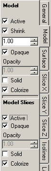
control panel Model is used to adjust the parameters relevant for the
visualisation of modelled building construction - in addition or in combination
with other
evaluations.
The
control panel Model is used to adjust the parameters relevant for the
visualisation of modelled building construction - in addition or in combination
with other
evaluations.
Following combination of evaluations might be of special interest:
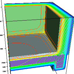
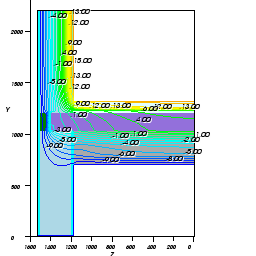
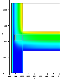
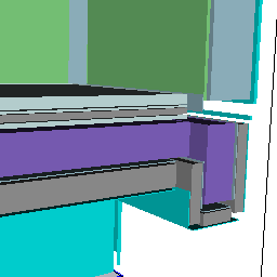
- View of the model shown as solid body with isolines (e.g.. isotherms) on component's surface,
- View of slices through the model (solid body) with isolines on slice planes,
- View of the model as lines (boundaries of materials) overlay-ed with other evaluations.
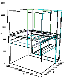
The model representation shown corresponds to the one used in Elements 3D window within input part. The resulting image shows the modelled construction resulting from the overlapping of input elements (the entry point for the so called "minimum grid").
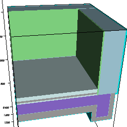
Surfaces of the model (and eventually edges) are shown colorized. Colorizing corresponds to the input of element properties.
The Slice planes X/Y/Z can be also shown as model slices. Resulting representation can be shown as solid (colorized by material colour) or edge-lines (i.e. material edges).
| Active,
Opaque, Colorize |
Decide about the visibility, colorizing and transparency of model surfaces (and its edges if applicable) |
| Shrink |
Elements will be "shrunken" towards their centre (the value of 1.0 means no shrinking). Shrunken view is very helpful when examining the modelled construction in its interior also. |
| Solid | Allows the wireframe view of edges of the model input. |
By default the construction model is shown as lines (wireframe) resulting from the input of elements.
The view onto edges of slice planes (these are located at the surface of the model) can be turned on or off within the control panel „Surface“. This is important ion the context of wireframe view of the modelled construction to either show lines coloured by material or by selected evaluation function.
By default the view of model slices is turned off or set to wireframe. This is required to avoid overlapping of that representation with slices of selected function and to avoid confusing results and interpretation difficulties when too many lines are simultaneously shown during initial display.
Remark: Planes representing construction surface and model
surface overlap. These can lead to visually "confusing" effect of "shadows"
shown on the surfaces. Therefore it is advised to select wireframe
representation for one of the two surface evaluations.
Important: Some (external) material edges overlap with surface edges and
slice edges. If all these are turned on the overlapping might result in visually
"confusing" effects.
Important: Model slice plane and function slice plane overlap. When both
are turned on this overlapping will lead to sometimes confusing effect of
"shadows". To make model slices visible at their own make slices itself fully
transparent (i.e. turn their opacity = 0). If you wish to view slices through
function values, it is advised to show model slices as lines (wireframe, solid
off) to show edges of materials only.
Important: To properly show lines at material edges elements of the
modelled construction are shrunk by a very small factor – otherwise the edges of
neighbouring elements could not be shown properly (visually confusing result,
possibly some lines even not visible). The shrinking factor used has a value of
0.99999, i.e. an element of 10 meters length is shrunken by less then 1 mm (only
in the picture,
which is absolutely invisible).
See also: Results 3D window, Active (setting), Opaque and Opacity (setting), Colorize (setting), Solid or Wireframe (setting), General (control panel), Isolines / Isotherms (control panel), Elements 3D window